SHIPPED · DS · 2026
Custom driver station
A purpose-built driver station for the team — laid-out controls, integrated HawkLights, and a housing that survives a competition pit instead of a laptop balanced on a cart.
- CAD
- Fabrication
- Embedded
- C
- Python
- Java
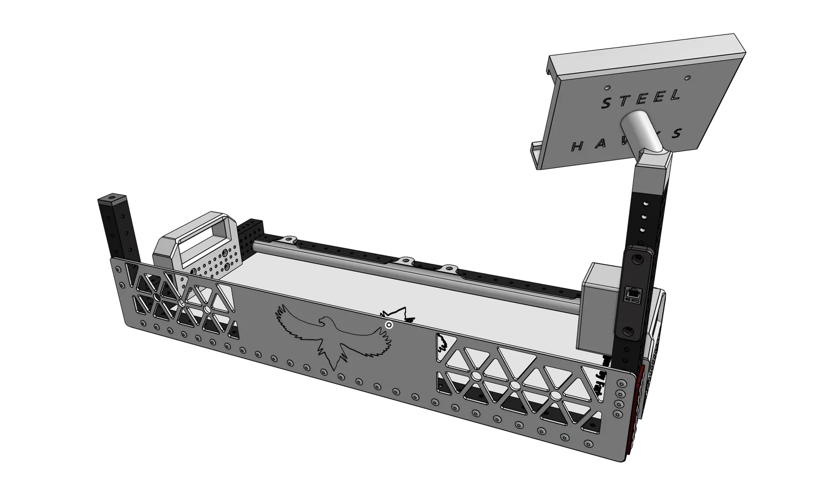
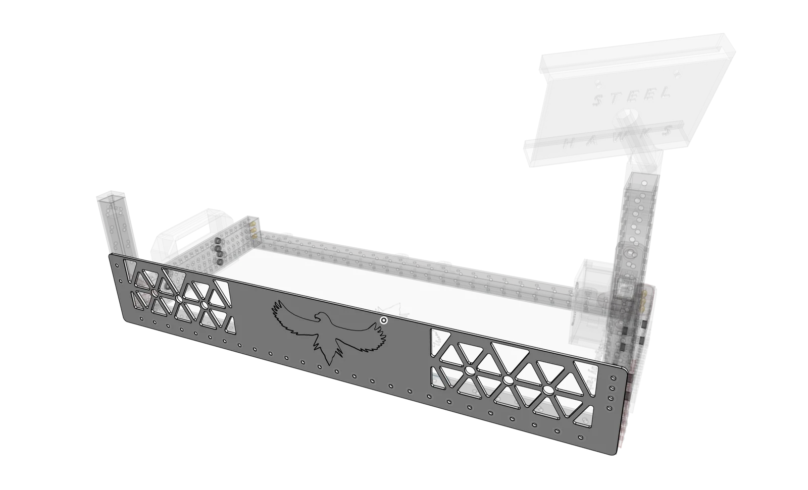
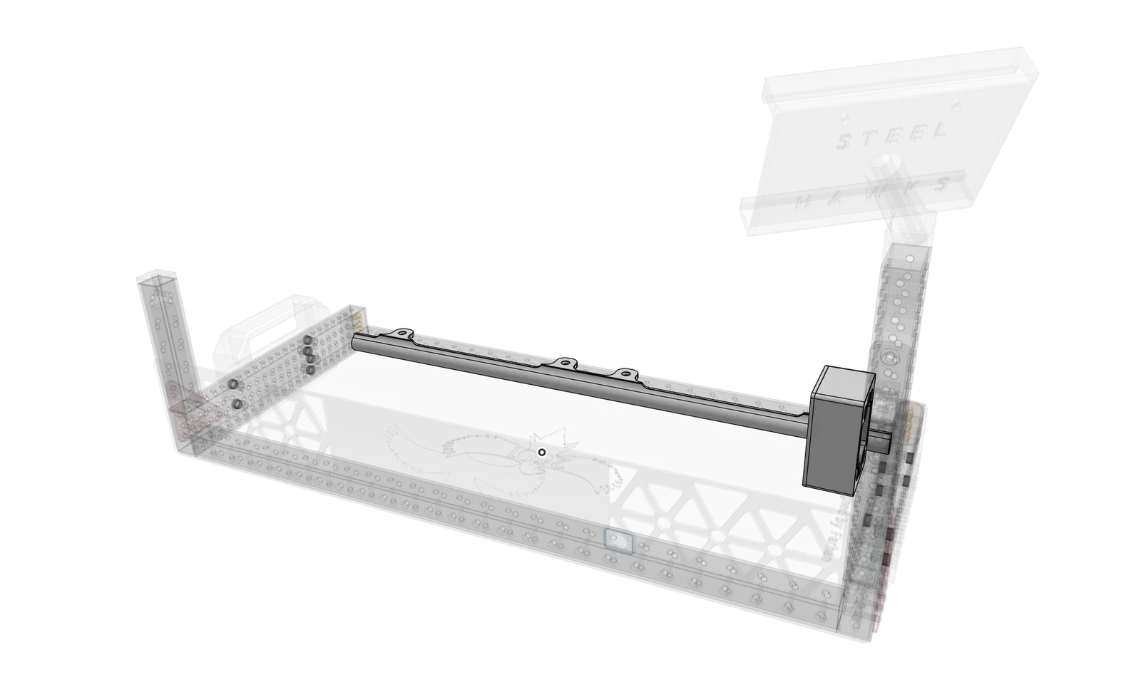
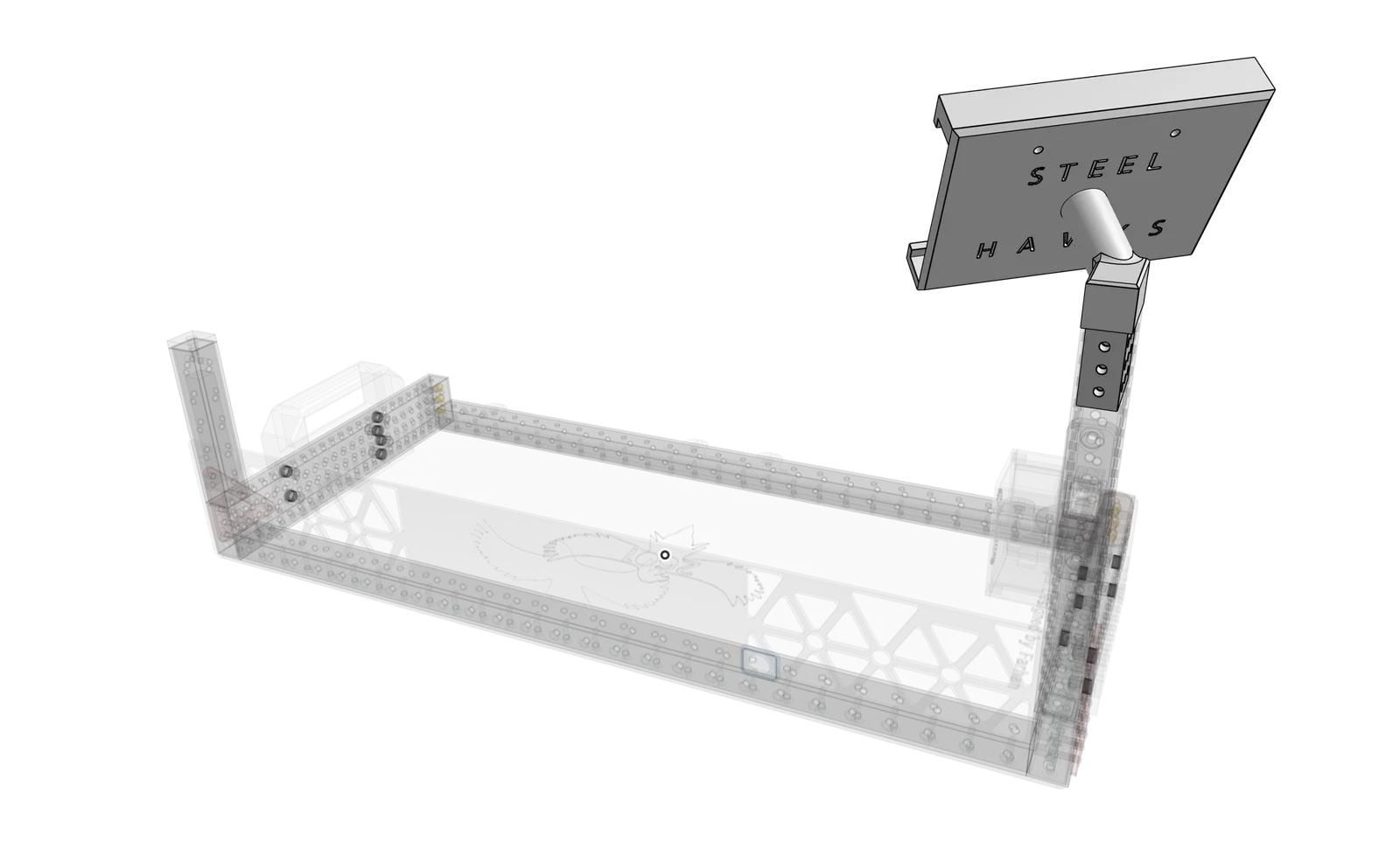
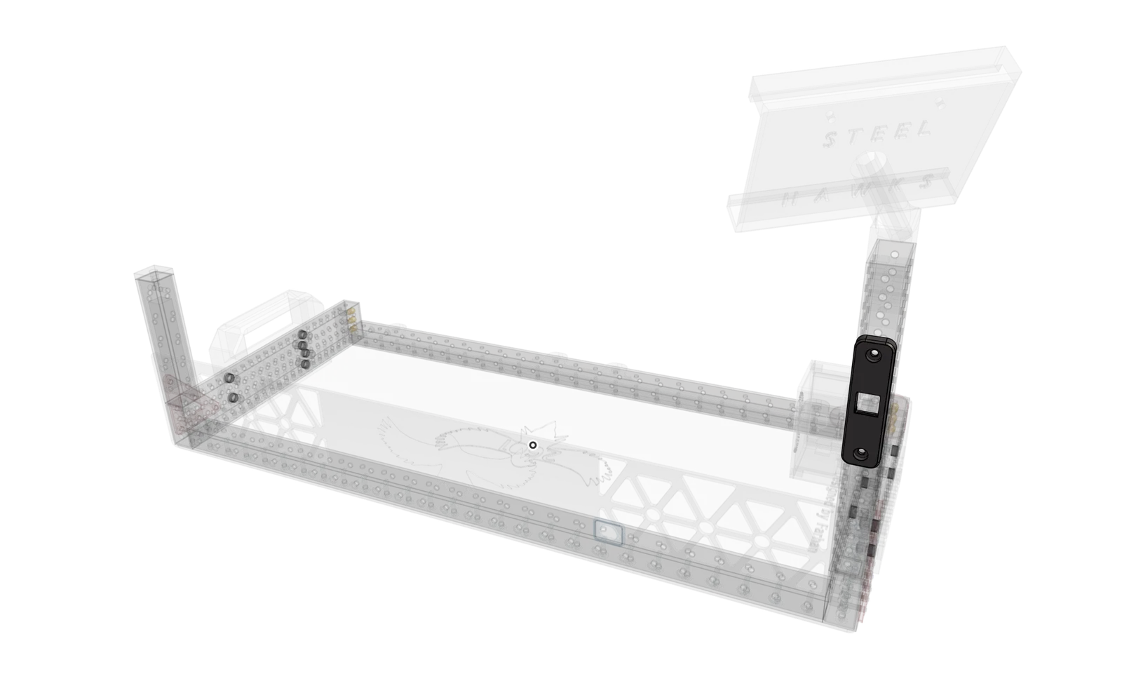
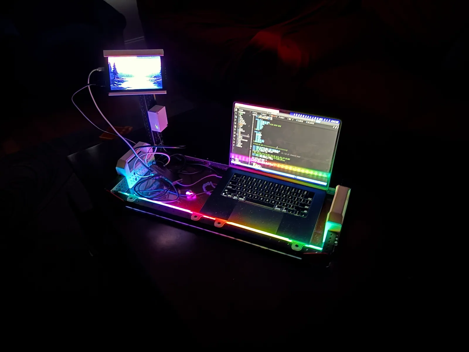
Most teams run a match off a laptop balanced on a cart. This is a purpose-built driver station: a fixed control layout, integrated HawkLights, and a housing built to take a beating in the pit.
The build
why
This started right after Worlds. The season was over, I was already missing robotics, so I decided to design and CAD a new driver station.
The one we had was built out of Lexan, and none of it had ever been CAD’d. The worst part was holding it. None of the Lexan edges were designed with hands in mind, so if you held it for very long they dug into your palms like a blade. I was Steel Hawks’ technician, so I knew that pain firsthand.
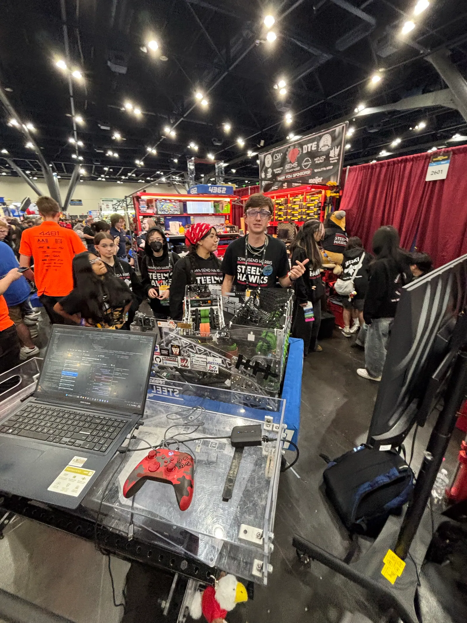
That’s the only photo I have of the old station. It’s also me as technician for my last match ever in FRC.
the frame
The frame is 2x1 and 1x1 aluminum tube. I spray painted the tubes black and the gussets red.
Once the paint was fully dry, I drilled 9/32” holes and set eight nut rivets. The handle bolts onto the 2x1 tube with M5 Torx screws.
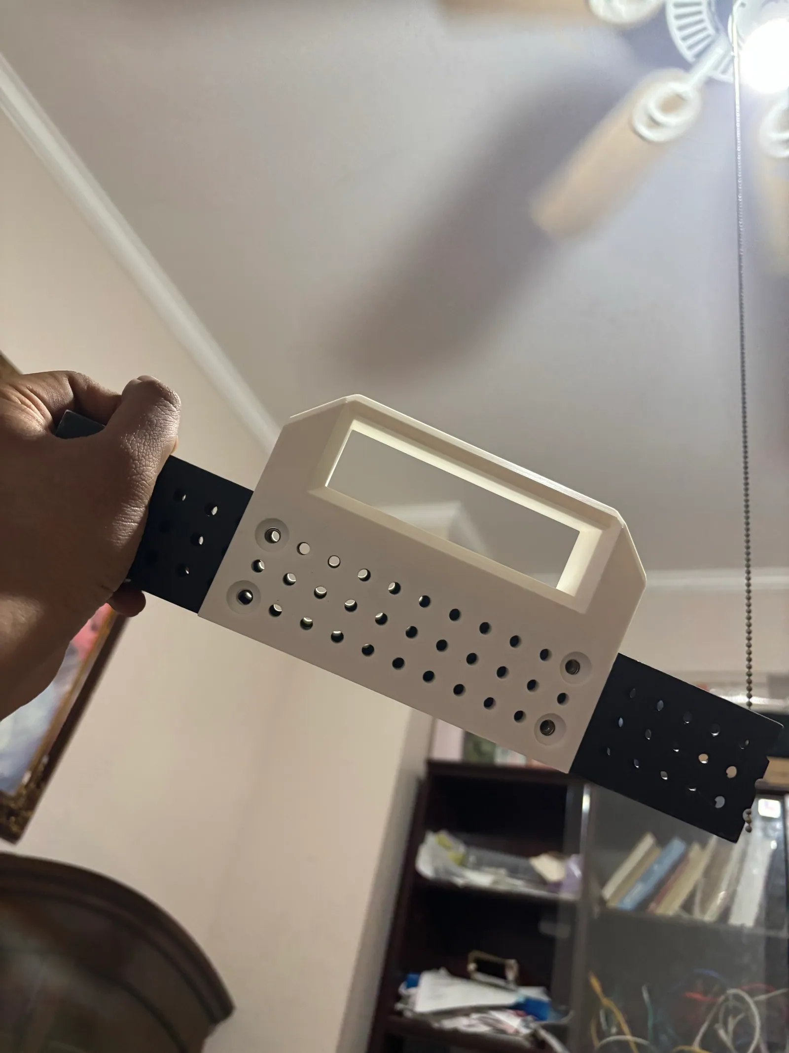
the bottom plate
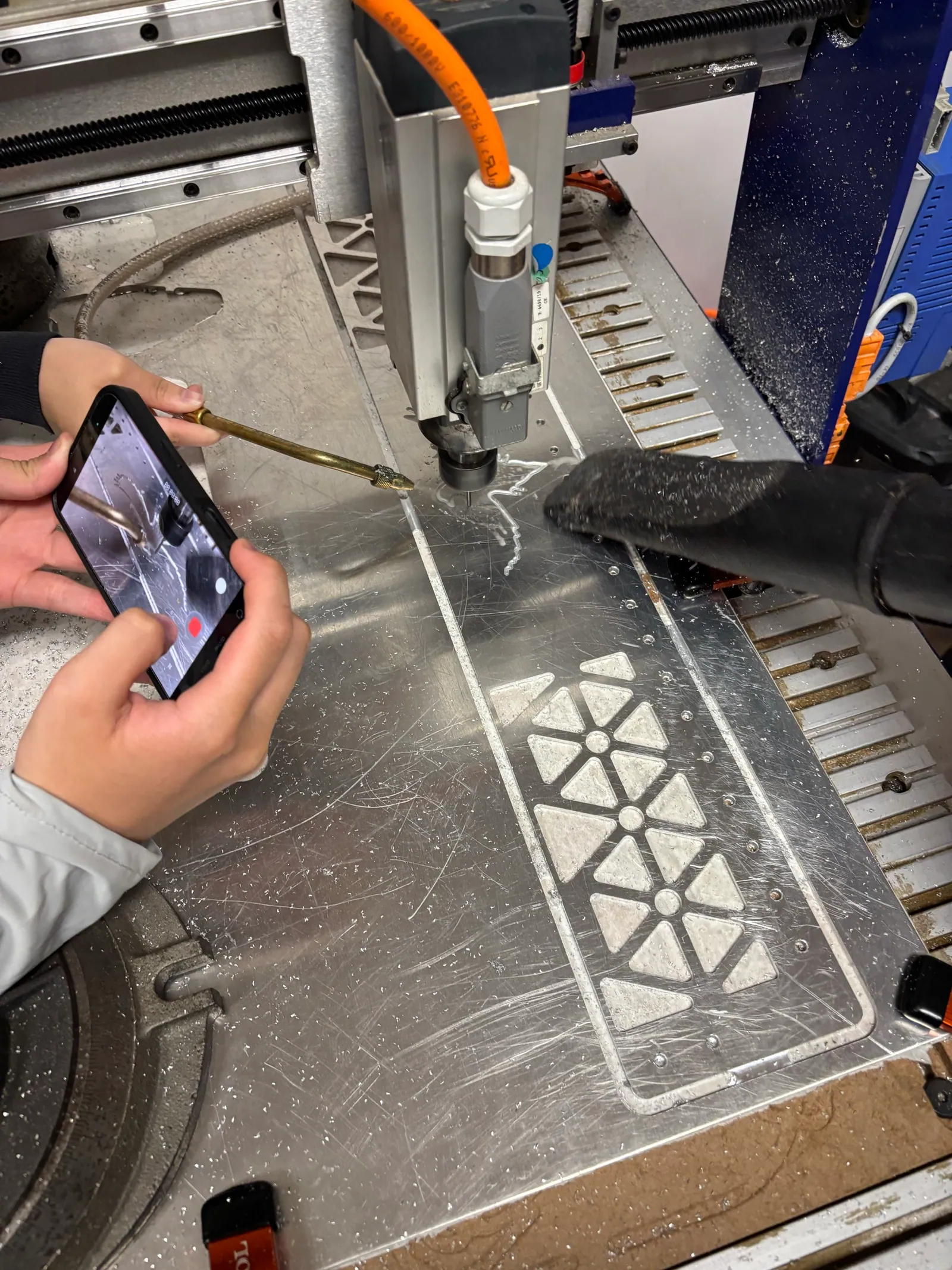
The bottom plate is Lexan, CNC’d with a hawk and “designed by farhan” engraved into it.
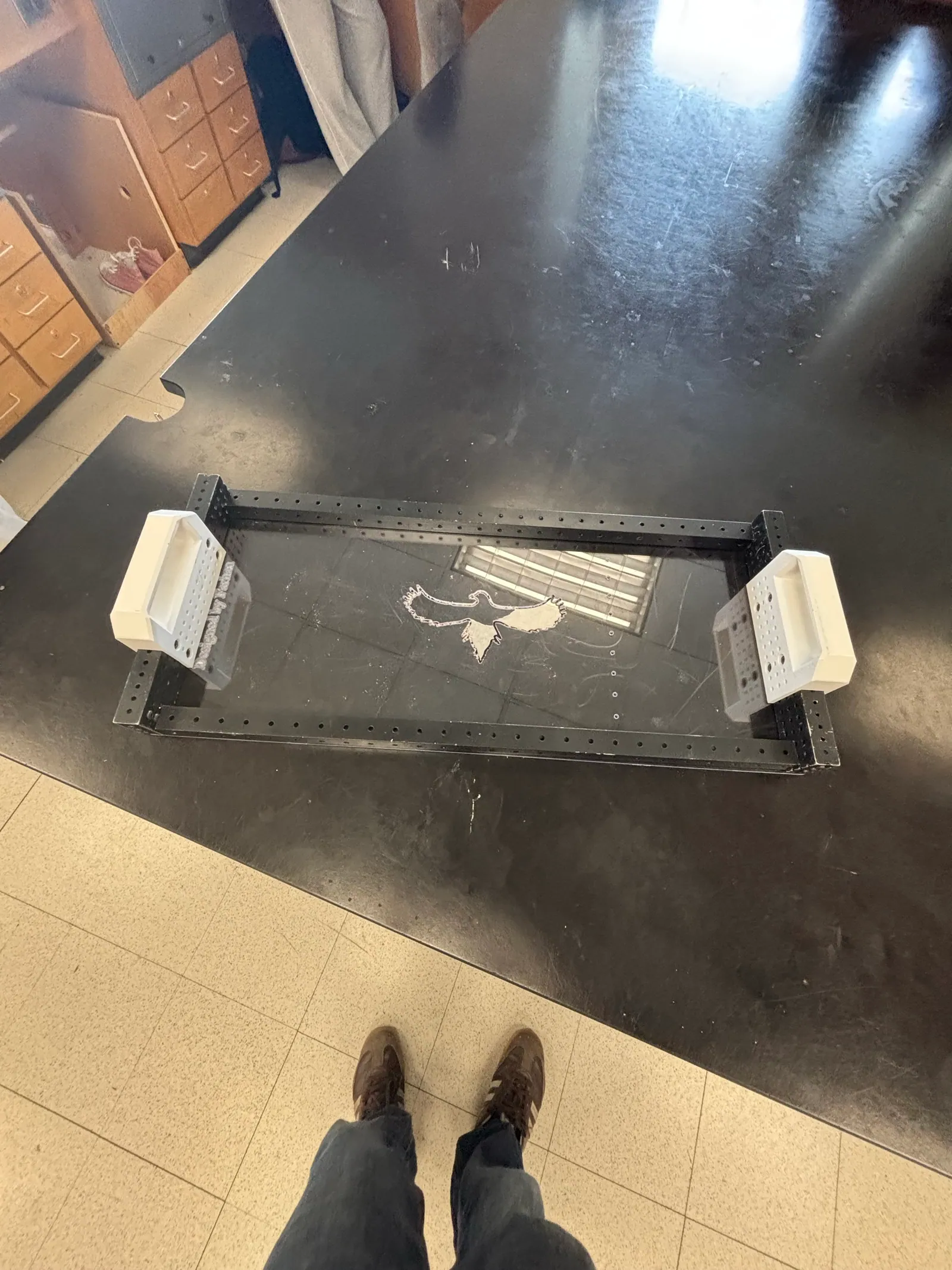
With the plate done, I set everything together without any fasteners to see how it would look:
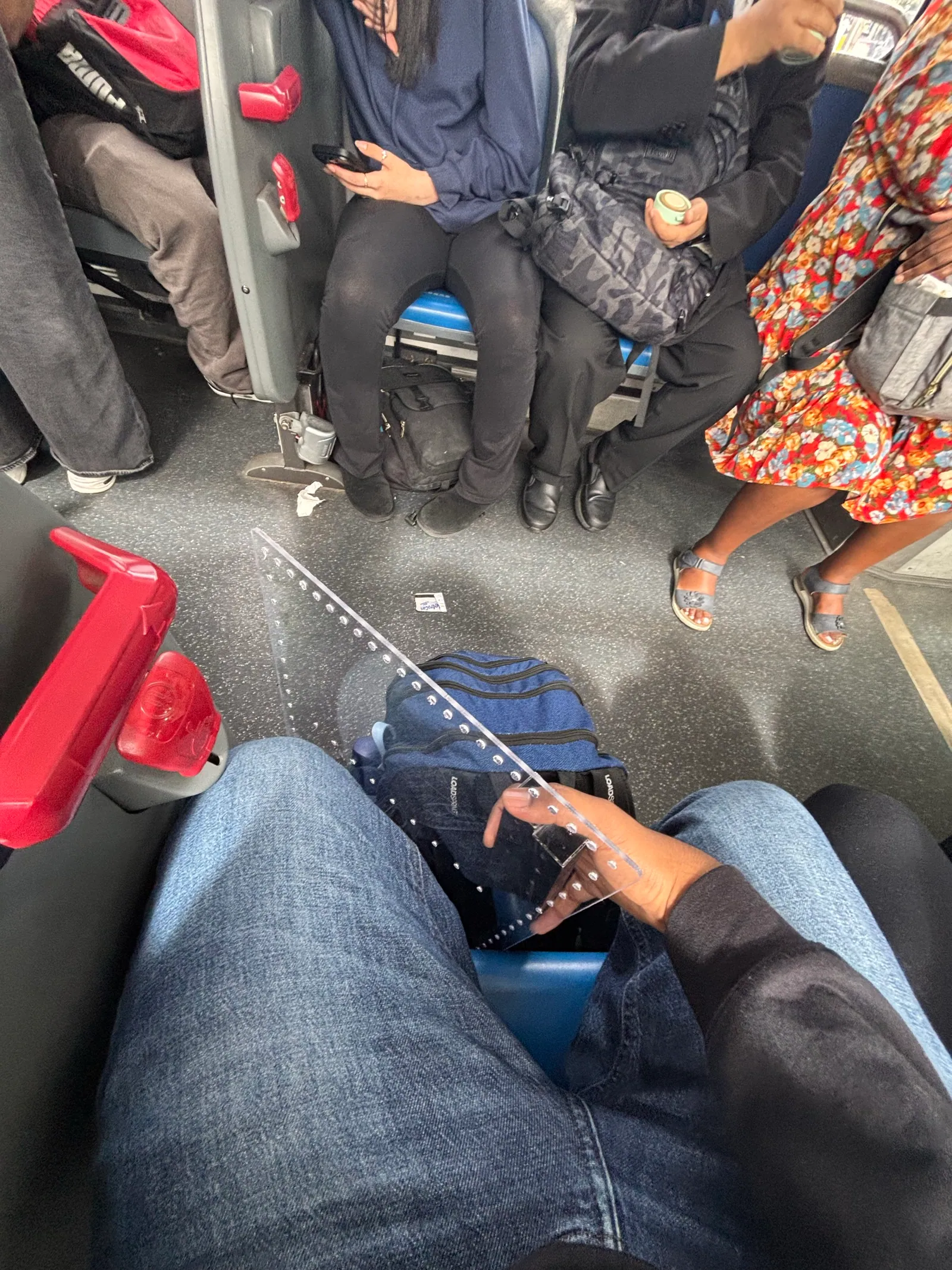
Then I took the plate home on the bus, which is not a small thing to do with a sheet of Lexan that size:
At home I riveted the frame down with 3/16” rivets. Every hole had to be drilled out to clearance and then reamed to clean up the excess material.
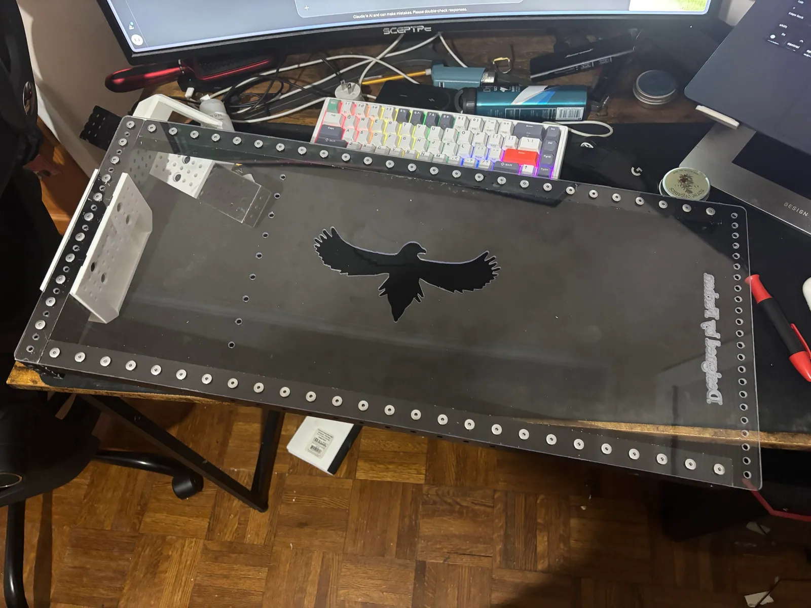
About the hawk. It was only supposed to be cut halfway into the Lexan, but the CNC went all the way through, leaving a big hawk-shaped hole in the plate. We knew that at the time. The damage was already done, so we kept moving forward, and I figured I could live with the hole.
I couldn’t. The inner profile of the hawk was sharp, and I cut myself on it, which PISSED me off! On top of that, things kept dropping out through the hole. So I drilled every rivet back out, cleaned up the scuffs that left behind, and we recut the plate with the hawk only cut halfway in, the way it was designed.
wire holes
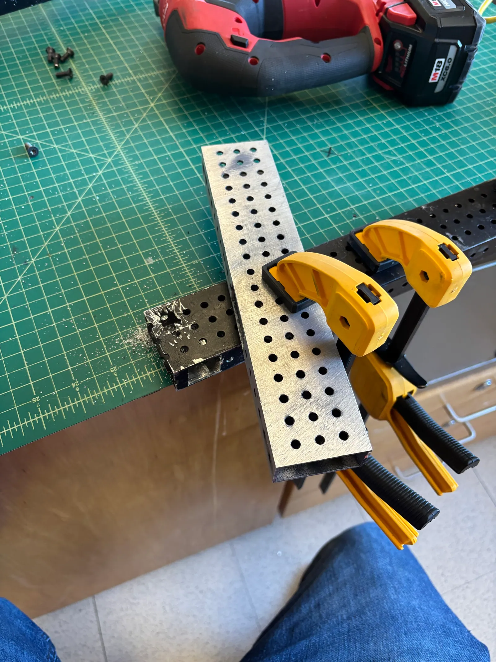
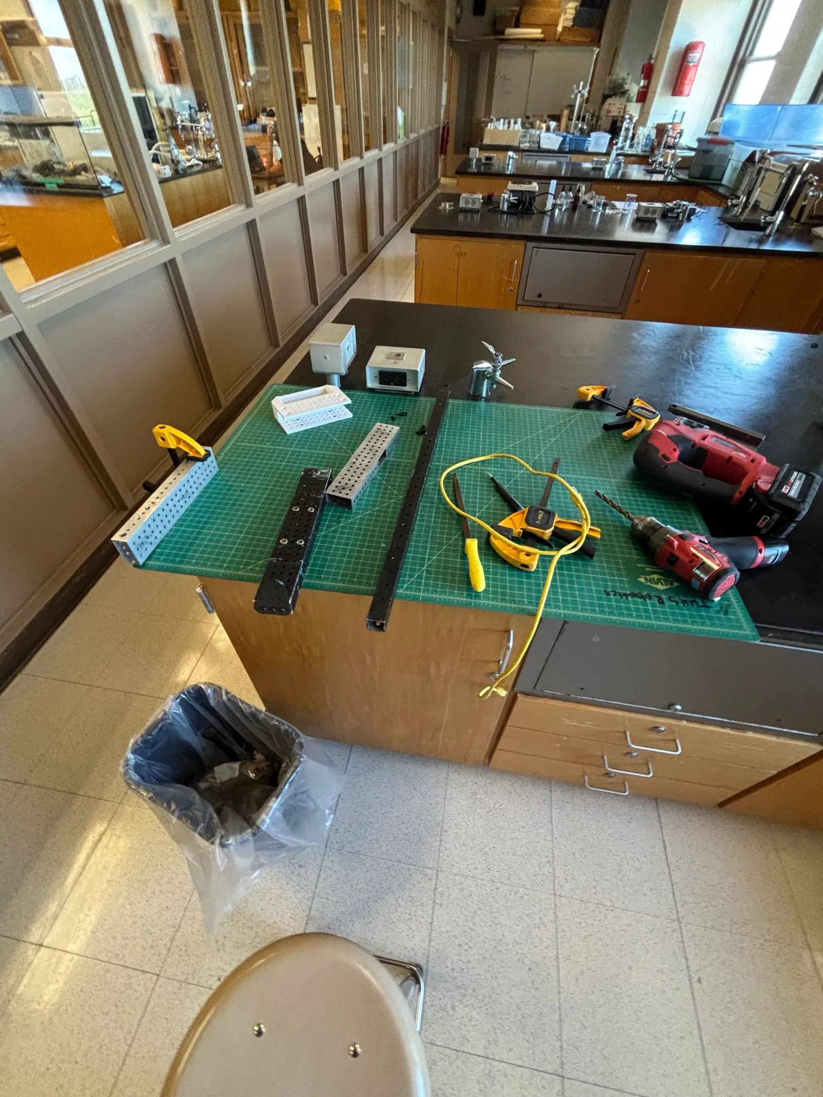
The wires run inside the tubes, so the tubes needed holes to pass them through. I cut those in the school lab with a jigsaw, and I did it in a way that was, honestly, quite dangerous. Do not do what I did.
ethernet and screen
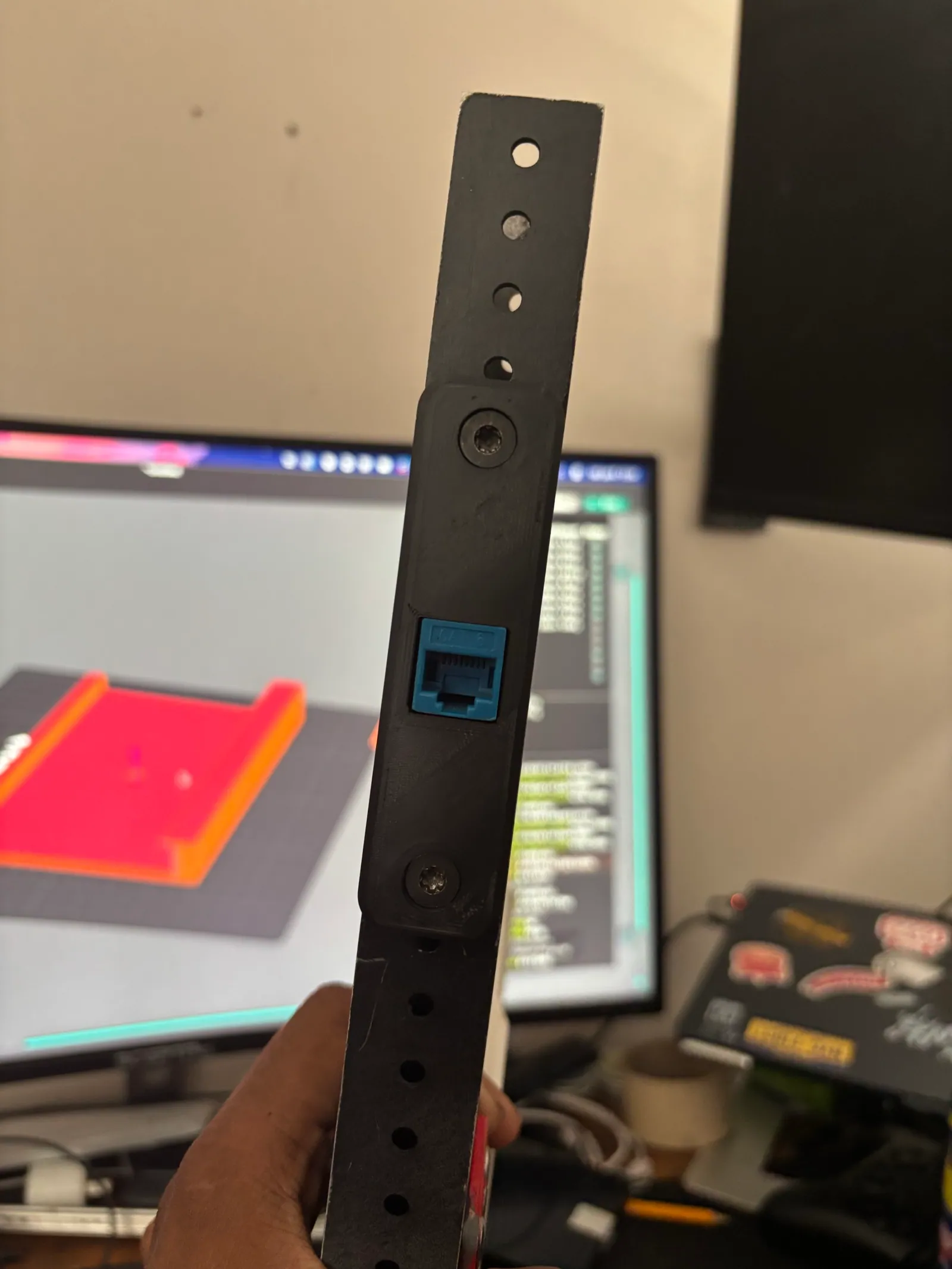
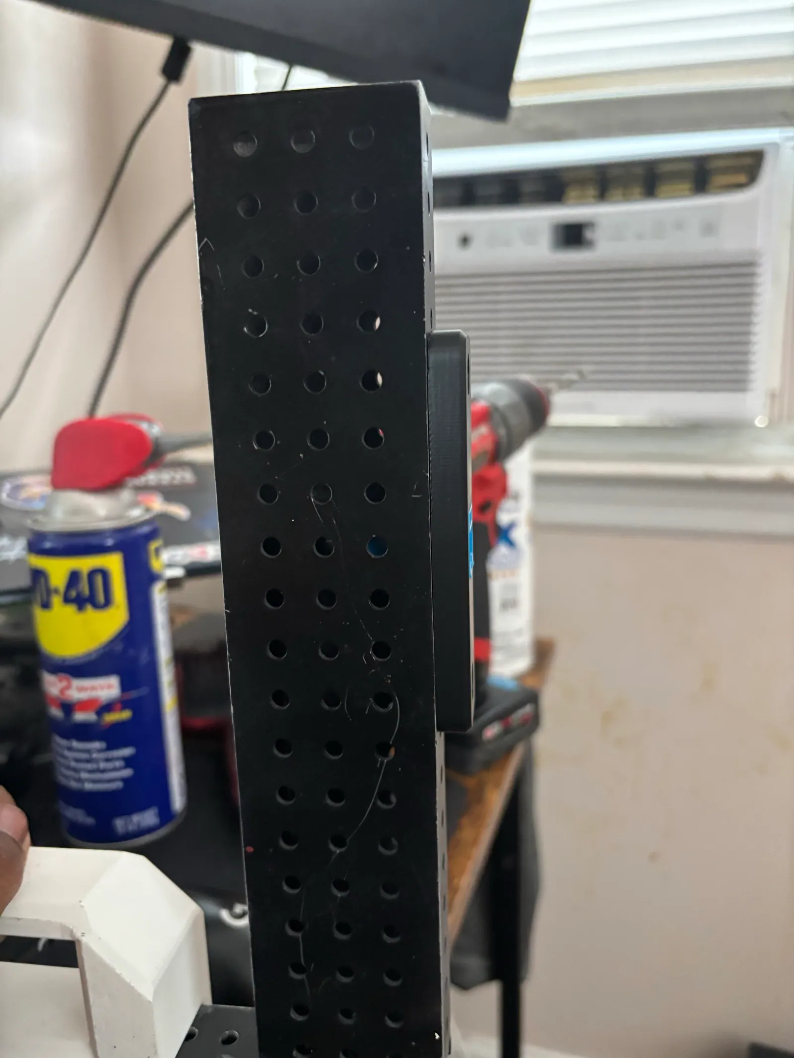
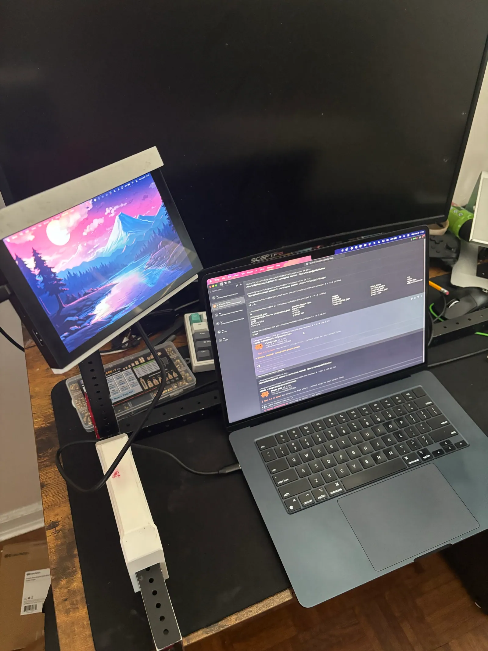
An Ethernet port is mounted in the side of the vertical 2x1 tube. On top of that tube, a 3D printed mount holds a 7” screen.
the light bar
The LEDs are WS2812Bs run by a Raspberry Pi Pico running C (more on that code below). This is the wiring and firmware prototype working for the first time:
Then I had to work out where the LEDs would actually go. My first try copied what I believe RoboTigers do on their driver station: LEDs inside the tubes, shining out of the holes. But their tubes are clear, and ours are painted-black aluminum. It didn’t work. Some holes were far too bright and others too dark, because the LEDs didn’t line up with the small 3/16” holes. It looked pretty bad.
The next logical step was to diffuse the light. That was by far the most frustrating part of the whole project. The diffuser’s distance from the LEDs had to be exactly right, and so did the print’s layer height. When I made the walls too thin, the prints came out cracked:
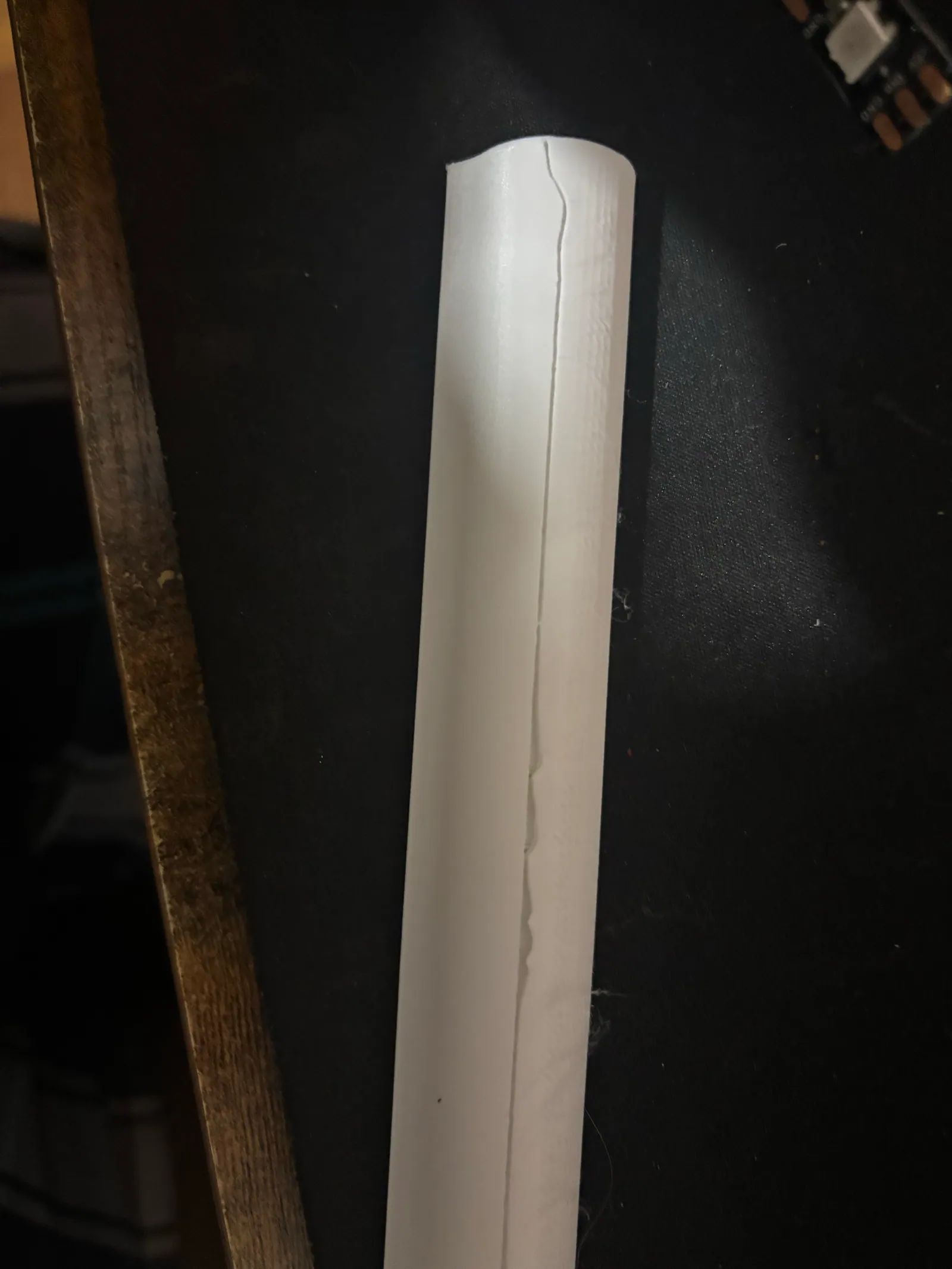
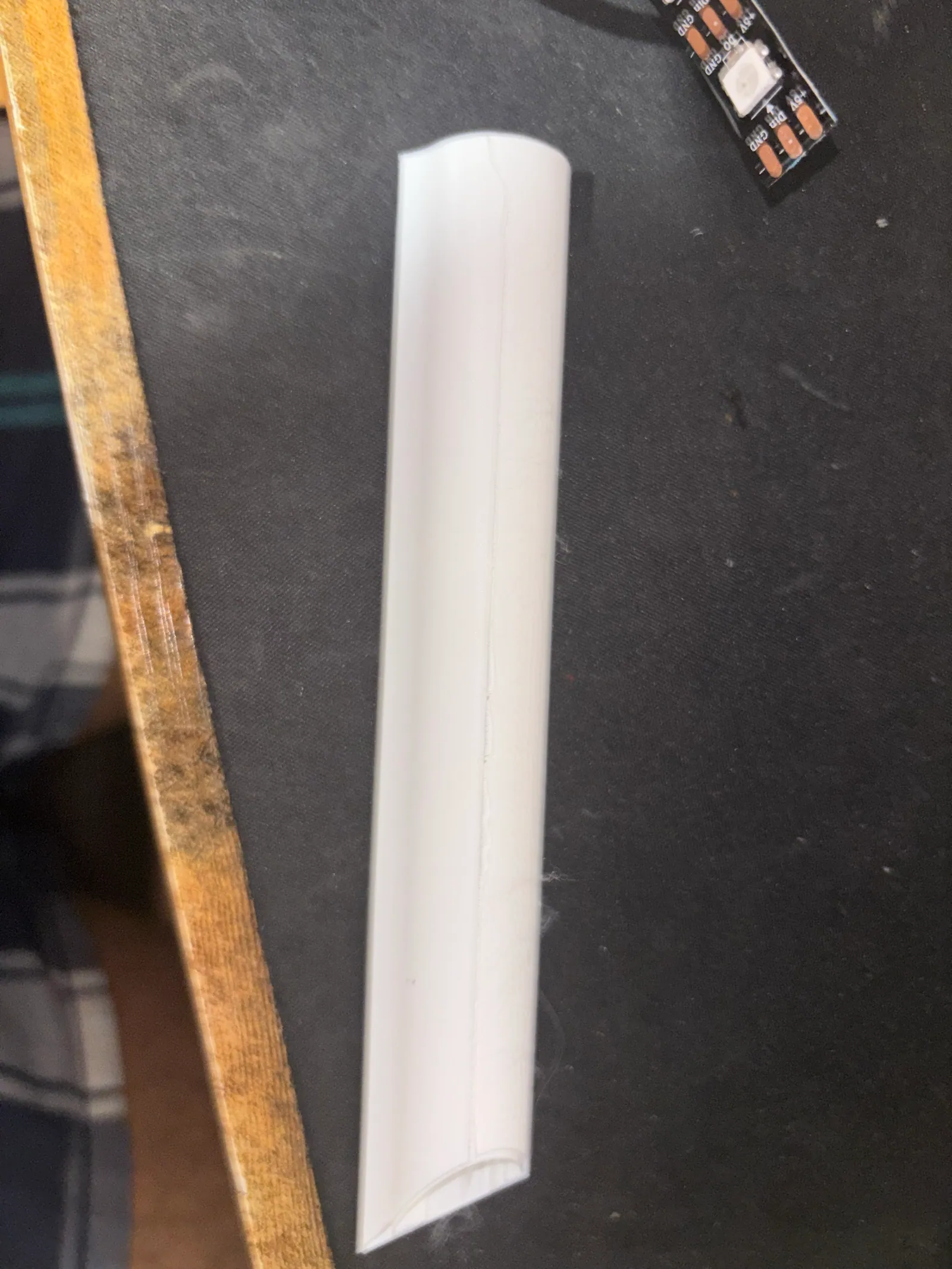
Another print failed overnight while I was asleep:
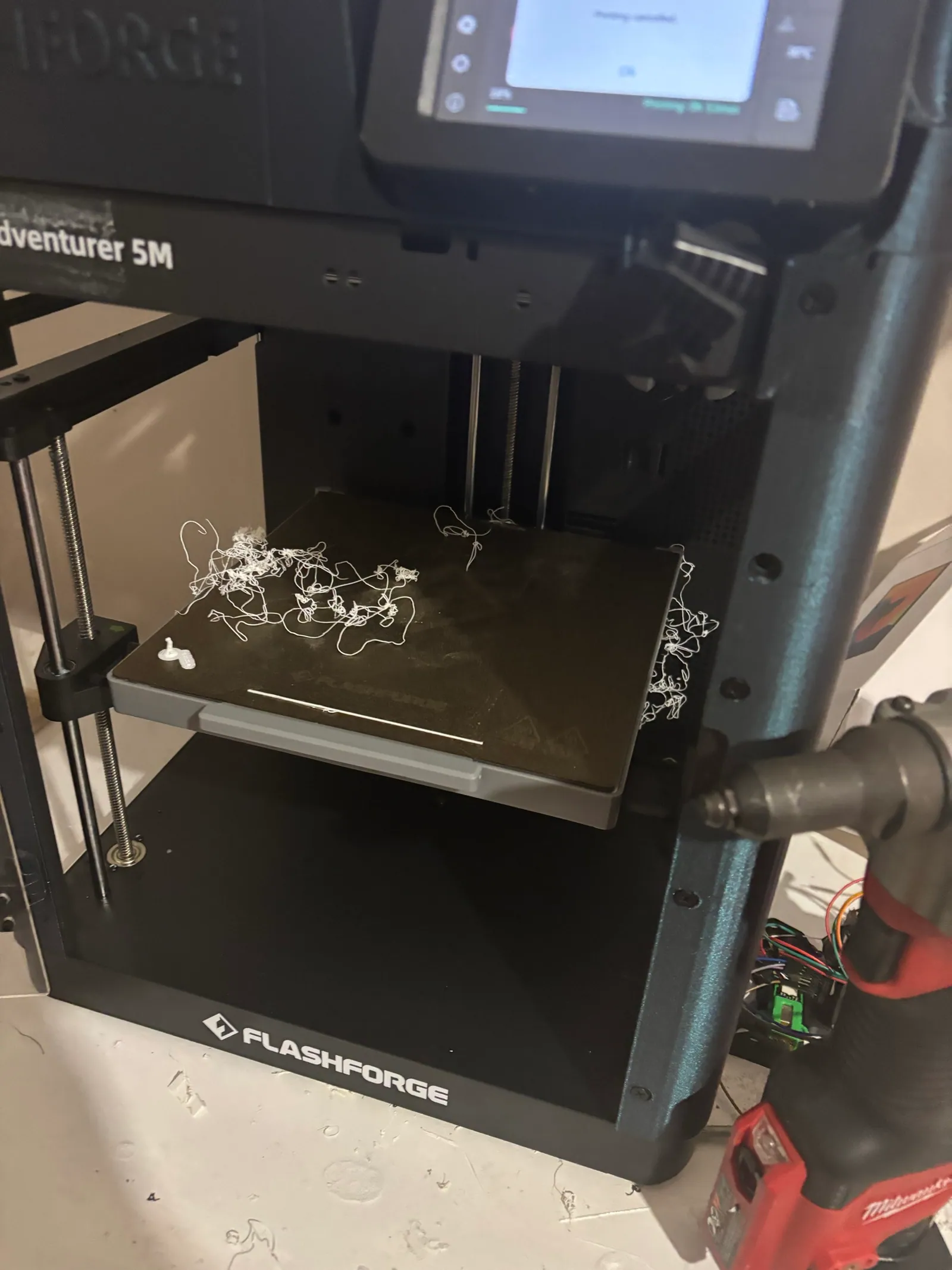
This one technically worked, but the diffusion was off. You could still pick out every single diode. It was also printed in three pieces and soldered together, which I didn’t like. So it was back to CAD again.
On top of all that, the diffuser is too long for my printer. Even angled 60° up on the bed it didn’t fit, so I had to split it into two parts and find a way to join them. First I designed a connector, but at those wall thicknesses it would never print right, no matter what I tried. Next I skipped the connector and welded the two halves with a soldering iron. That worked, but it looked horrible.
The fix ended up coming from how the diffuser was already mounted. It hangs from small cantilevered L-brackets that screw into the 1x1 tube and drop straight down. I just added two more of those brackets on either side of the split, so each half is supported right at the seam and there’s no joint to make.
wiring
WS2812Bs need three wires: +5 V, ground, and signal. A PWM cable carries exactly that, so I spliced one. Originally there were going to be two strips, but I was worried about hitting the current limit of the laptop’s USB port. Everything runs off that one port: the Pico plugs into the laptop, and the strip is powered from the Pico’s 5 V pin. The wires run inside the 2x1 tube out to the strip.
I probably should have added a capacitor across the strip’s power to smooth it out, but I didn’t feel like spending any more money. So sometimes the whole thing would brown out. Instead of a capacitor, I capped the brightness in software, just under the point where it started browning out.
the pico enclosure
The last printed part is a box for the Pico and the WAGO lever nuts that join it to the wires running out to the lights. There’s no screw or clip holding the Pico. It stands against the wall of the box with its micro-USB port facing straight down, and the cable leaves through a hole in the bottom. The plugged-in cable is what keeps it in place: it can’t slide backward or fall out, because the port holds the board hugged to the wall. I also designed it so you can reach the BOOTSEL button to flash new firmware without taking anything apart.
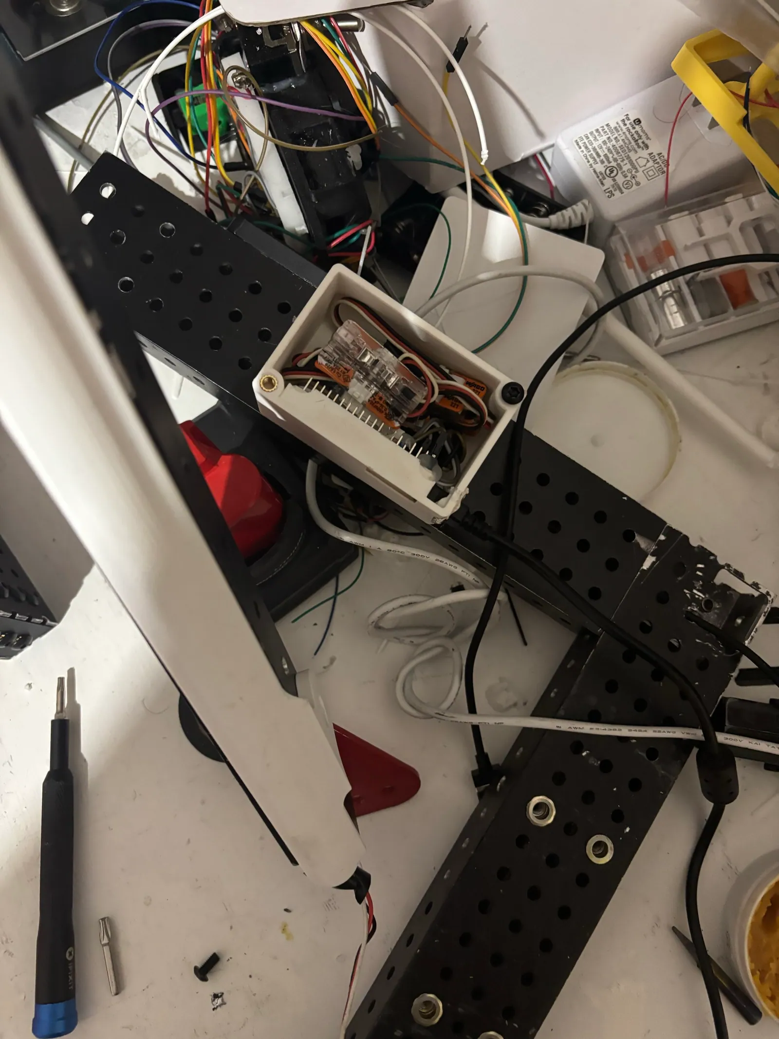
The lid screws down with M4 button-head Torx screws into two heat-set inserts. The box mounts to the vertical 2x1 tube with nut rivets and M5 countersunk Torx screws. With all of that done, everything got riveted onto the Lexan plate, and the station was finished:
the light bar running
ok, not quite finished
Remember that “finished”? I lied. The CAD had a metal plate across the back, and I still had to go back to school and CNC it out of 1/8” aluminum.
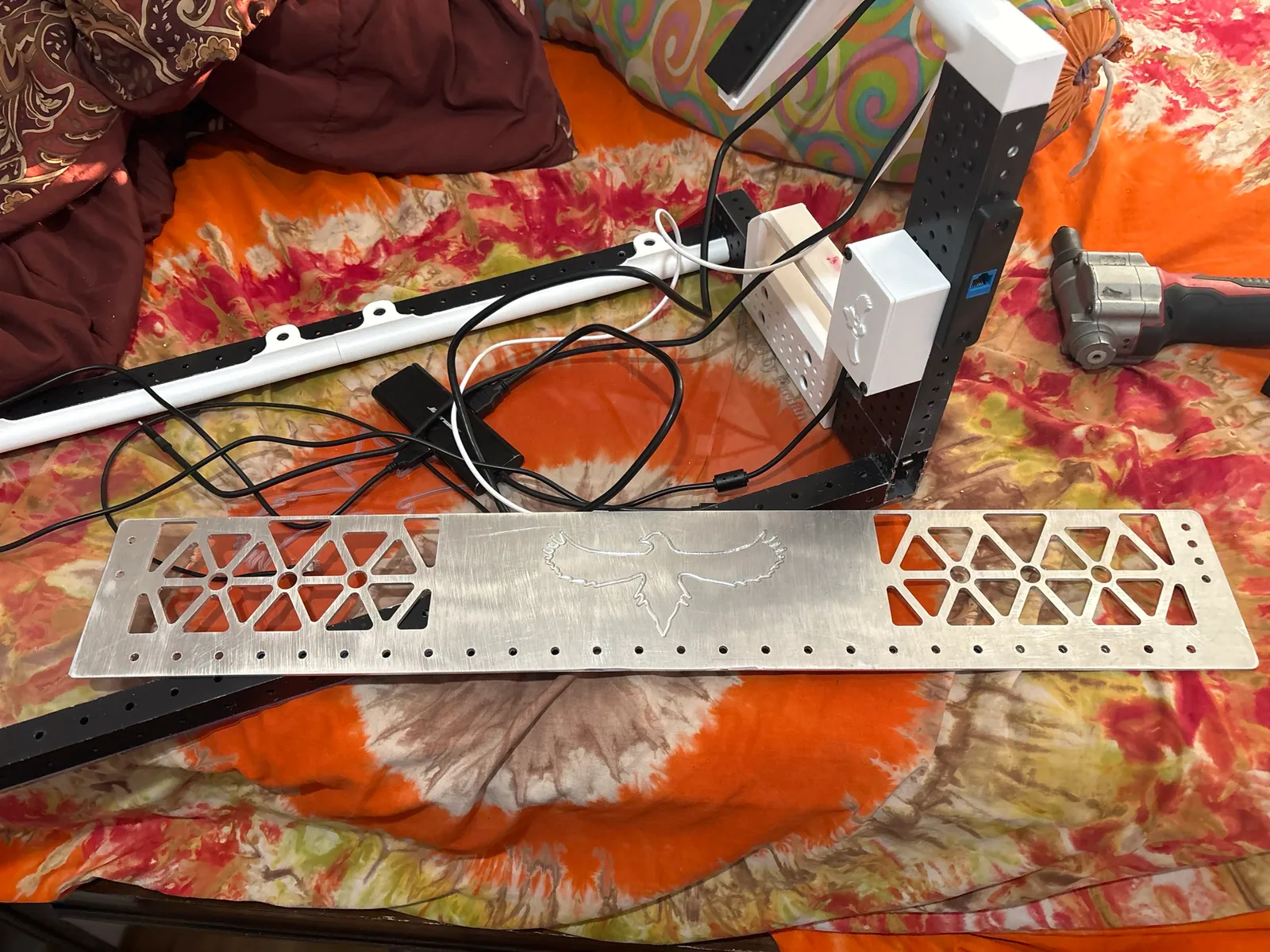
Bare, the aluminum looked pretty clean. I still painted it white, because white next to the red and black is our team colors and the contrast looks great.
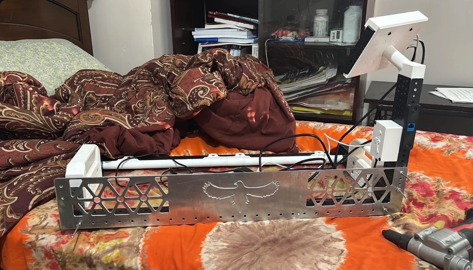
That’s the backplate held up by its rivets before they were popped, and before paint. For some reason I never took a photo of the station after that, with everything done.
LEDs
The strip on the station is 38 WS2812Bs driven by a Raspberry Pi Pico. The Pico sits in the driver station, not on the robot, so the robot has no wire to it. The only link between them is the laptop, and that shapes the whole thing. There are three pieces of code, one per hop:
robot code ──(NT /HawkLights)──▶ laptop bridge app ──(USB serial)──▶ Pico ──▶ LEDsThe robot only publishes intent to NetworkTables. The laptop app is a pump: NT in, serial out. The Pico renders the patterns, and it also decides what to show when nobody is telling it anything.
the robot library
On the robot side, HawkLights is a small Java package you copy into a robot project. Robot code
says what it wants with Triggers, and the highest-priority active request wins:
HawkLights leds = new HawkLights();

leds.setIdle(LedPattern.solid(Color.kBlue));
leds.bind(intake.hasNote(),  LedPattern.solid(Color.kOrange));
leds.bind(shooter.atSpeed(), LedPattern.flash(Color.kGreen, 120), LedPriority.HIGH);
leds.bind(climber.engaged(), LedPattern.rainbow(),                LedPriority.CRITICAL);
leds.bind(RobotModeTriggers.teleop(), LedPattern.matchTimer(), LedPriority.LOW);
Each binding becomes a startEnd command. It adds a request to a list when the trigger goes
true and removes it when the trigger goes false. The command deliberately requires no
subsystem. If it did, the scheduler would cancel one LED request whenever another started, and
there’d be nothing left to rank. Instead every active request sits in the list at once, and
periodic() picks the winner:
Request best = idle;
for (Request r : requests) {
  if (best == null || r.priority >= best.priority) {
    best = r;
  }
}
The >= makes ties go to whichever request became active most recently. The idle pattern sits
at priority -1000, so anything beats it. The winner goes out to the /HawkLights table as
plain values (state, r, g, b, intervalMs, and active). When nothing is requesting,
active goes false and the robot stops having an opinion.
The commands also run ignoringDisable(true). LEDs are status indication, and the moments you
most want them are when the robot is sitting disabled on the field.
the match timer
LedPattern.matchTimer() turns the strip into a countdown bar. Its length is a supplier that
checks DriverStation.isAutonomous(), so one binding spans 15 s during auto and 135 s during
teleop. The remaining time comes from DriverStation.getMatchTime(). On the bench that returns
-1, which would leave the bar empty, so there’s a fallback:
double matchTime = DriverStation.getMatchTime();
if (matchTime >= 0) {
  start[0] = -1; // re-arm the fallback in case the match clock drops out
  return matchTime;
}
double now = Timer.getFPGATimestamp();
if (start[0] < 0) {
  start[0] = now;
}
return Math.max(0, total.getAsDouble() - (now - start[0]));
Off the field clock, the bar starts its own countdown the first time it’s shown. Plug into FMS and the real clock takes over.
the bridge app
The laptop app is Python with a Tkinter GUI, packaged with PyInstaller into a .app for macOS
and an .exe for Windows. It connects to the robot with ntcore (by team number or IP) and
reads two things. The first is the /HawkLights table. The second is FMSInfo/FMSControlData,
the driver station’s control word, which it decodes into a robot state:
if cw & CW_ESTOP:
    return DSState.ESTOP
if not (cw & CW_ENABLED):
    return DSState.DISABLED
if cw & CW_AUTO:
    return DSState.AUTO
if cw & CW_TEST:
    return DSState.TEST
return DSState.TELEOP
So the robot library never has to publish its own mode; the bridge works it out on its own.
A background thread runs at 20 Hz. On every tick it sends a heartbeat. It sends the robot state
whenever it changes, and again at least once a second in case a byte got dropped. It also
re-sends whatever override is active. The GUI has manual controls and a small command console
(flash red 200, bounce green, clear) for bench testing. A local override from the GUI
beats the robot’s request, so you can test the strip with the robot still running.
The packaged app has to bundle ntcore’s native libraries, and a frozen build fails quietly if
they’re missing. So main.py takes a --selftest flag that just tries import ntcore and
reports the result.
the wire protocol
Laptop to Pico is USB serial with a tiny binary protocol. Every message has a fixed length, and the first byte says which message it is:
0x00 HEARTBEAT  [0x00]
0x01 DS_STATE   [0x01][state]
0x02 OVERRIDE   [0x02][pattern][r][g][b][interval_hi][interval_lo]
0x03 TIMER      [0x03][rem_hi][rem_lo][tot_hi][tot_lo]
The Pico reads the type byte, knows how many bytes to wait for, and drops any byte that isn’t
a valid type. That’s how it resyncs if it ever lands mid-message. Timer values travel as
deciseconds in a uint16, so a match clock fits in two bytes with tenth-of-a-second resolution.
There’s no “clear” message. An override only lasts while the bridge keeps re-sending it, and the Pico runs two timeouts:
// general liveness: any message keeps the link alive
if (now - last_message_ms > MSG_TIMEOUT_MS) {
    ds_current_state = STATE_DISCONNECTED_DS;
    ds_state_switcher_allowed = true;
}
// override liveness: overrides decay back to pico fallback on silence
if (now - last_override_ms > MSG_TIMEOUT_MS) {
    ds_state_switcher_allowed = true;
}
Silence is the clear. If the robot stops requesting, if the bridge crashes, or if someone yanks the USB cable, the strip falls back within a second without anyone having to send anything. A protocol with an explicit clear would leave the strip stuck on its last pattern in exactly the cases where the clear never arrives.
the firmware
The Pico firmware is C on the Pico SDK, with a 50 Hz main loop. It polls serial, then decides what to draw. When no override is live, the Pico falls back to showing the connection state on its own:
- laptop not talking (no bytes for 1 s): slow red flash, and the Pico’s onboard LED blinks
- laptop up, robot unreachable: solid red
- robot connected and disabled: rainbow
That means the strip is always saying something useful, even with no robot code running at all.
The WS2812B timing comes from the RP2040’s PIO, a small state machine that bit-bangs the 800 kHz
signal without the CPU. It’s the standard ws2812.pio program from the Pico examples. The bug I
hit was in packing the pixels. WS2812Bs want GRB, not RGB, and the PIO shifts out
the top 24 bits of each 32-bit word. The first version packed r << 16 | g << 8 | b, which put
the colors in the wrong order and in the wrong place in the word. The fix:
static inline uint32_t rgb_pack(uint8_t r, uint8_t g, uint8_t b) {
    // WS2812B expects GRB, MSB first. The PIO shifts out the top 24 bits
    // (shift-left, autopull threshold 24), so pack GRB into bits 31..8.
    return ((uint32_t)g << 24) | ((uint32_t)r << 16) | ((uint32_t)b << 8);
}
The patterns are solid, flash, fade, rainbow, bounce, left and right indicator waves, and the timer bar. The timer bar has one detail worth mentioning. With 38 LEDs across a 135 s teleop, a whole pixel would drop off every ~3.5 s, which looks like a glitch. So the fill is computed in 1/256ths of an LED, and the boundary pixel is dimmed by the fraction:
uint32_t fill = (uint32_t)(((uint64_t)time_remaining_ms * NUM_LEDS * 256) / match_length_ms);
int full = (int)(fill >> 8);    // fully-lit LEDs
uint8_t edge = fill & 0xFF;     // brightness of the boundary LED
The trailing edge fades out smoothly instead of stepping. With 30% of the span left, the bar turns amber and starts breathing, about once a second, so the driver can tell it’s endgame from the corner of their eye.